In this tutorial we will learn how to make a weather station that will display a TEMPERATURE, HUMIDITY AND PRESSURE on the LCD Display TFT 7735
Watch a demonstration video.
Step 1: What You Will Need

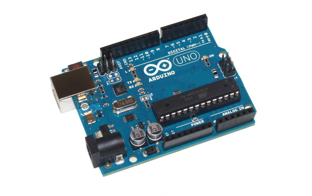
- Arduino UNO (Or any other Arduino)
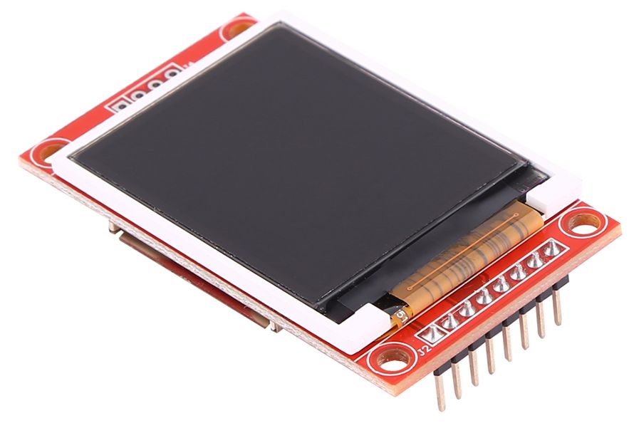
- LCD Display TFT 7735
- BMP280 Sensor
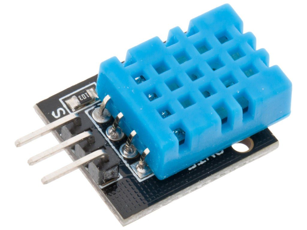
- DHT11 Sensor
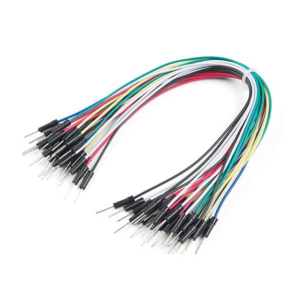
- Jumper wires
- Breadboard
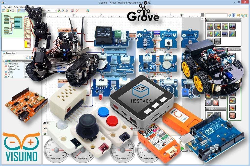
- Visuino program: Download Visuino
Step 2: The Circuit

LCD TFT ST7735
Connect:
- 1.8 TFT Display PIN [LED] to Arduino PIN [3.3 V]
- 1.8 TFT Display PIN [SCK] to Arduino PIN [13]
- 1.8 TFT Display PIN [SDA] to Arduino PIN [11]
- 1.8 TFT Display PIN [A0 or DC] to Arduino PIN [9]
- 1.8 TFT Display PIN [RESET] to Arduino PIN [8]
- 1.8 TFT Display PIN [CS] to Arduino PIN [10]
- 1.8 TFT Display PIN [GND] to Arduino PIN [GND]
- 1.8 TFT Display PIN [VCC] to Arduino PIN [5V]
NOTE: Some Arduino boards have different SPI pins so make sure you check your board documentation.
BMP280 Sensor
- Connect pin [VIN] to Arduino [V5]
- Connect pin [GND] to Arduino pin [GND]
- Connect pin [SDA] to Arduino pin [SDA]
- Connect pin [SCL] to Arduino pin [SCL]
DHT11 Sensor
- Connect pin [+] to Arduino [V5]
- Connect pin [-] to Arduino pin [GND]
- Connect pin [S] to Arduino digital pin [7]
Step 3: Start Visuino, and Select the Arduino UNO Board Type
To start programming the Arduino, you will need to have the Arduino IDE installed from here: https://www.arduino.cc/.
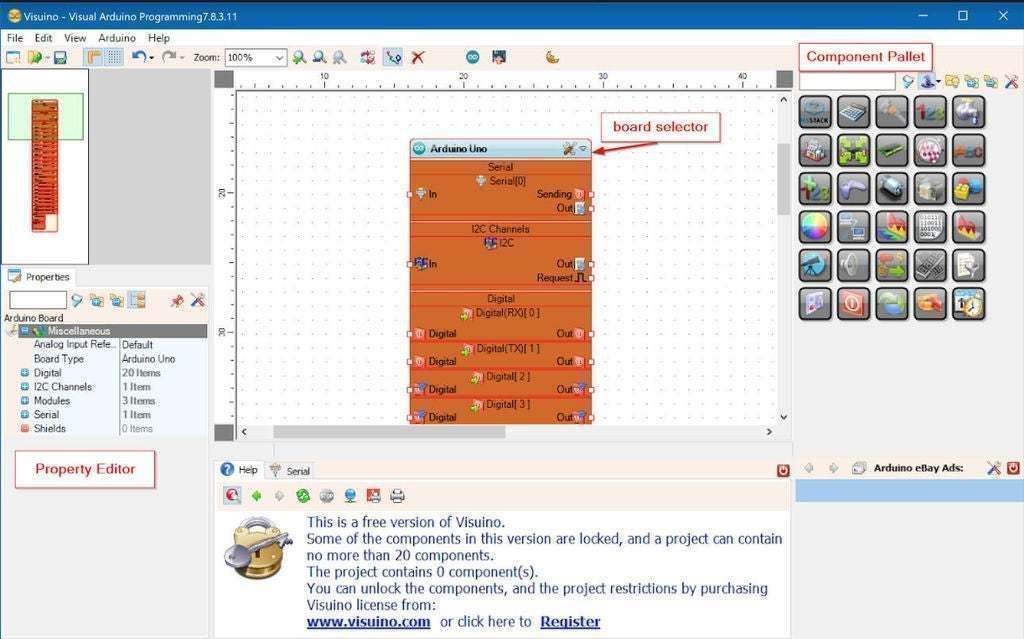
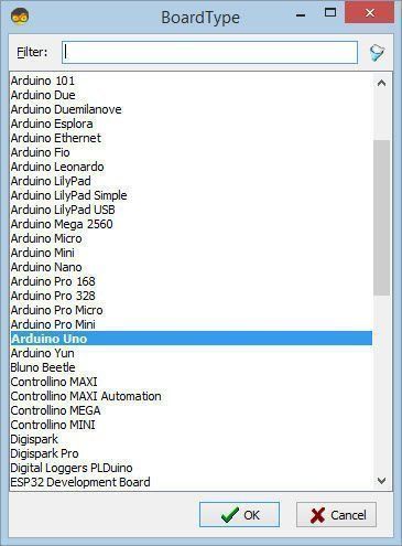
Please be aware that there are some critical bugs in Arduino IDE 1.6.6. Make sure that you install 1.6.7 or higher, otherwise this Instructable will not work! If you have not done follow the steps in this Instructable to setup the Arduino IDE to program Arduino UNO! The Visuino: https://www.visuino.eu also needs to be installed. Start Visuino as shown in the first picture Click on the “Tools” button on the Arduino component (Picture 1) in Visuino When the dialog appears, select “Arduino UNO” as shown on Picture 2
Step 4: In Visuino Add Components
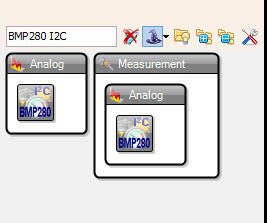
- Add “Pressure Temperature BMP280 I2C” component
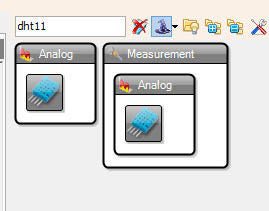
- Add “Humidity and Thermometer DHT11/21/22/AM2301” component
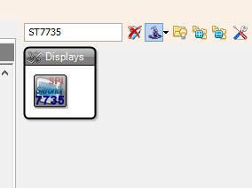
- Add “TFT Color Display ST7735” component
Step 5: In Visuino Set Components
- Select “Display1” and set “Orientation” to goDown (this will change the directon of displaying)
Note: In case the display would not work try changing the Type under the properties window
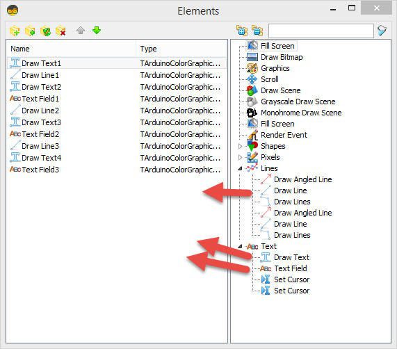
- Double click on the “Display1” and in the elements window expand “Text” and “Lines” on the right side and drag to the left side:
- 4X “Draw Text”
- 3X “Draw Line”
- 3X “Text Field”
On the left side select:
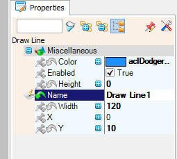
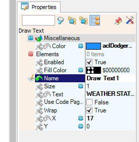
– “Draw Text1” and in the properties window set “Size” to 1, “Color” to aclDodgerBlue and “X” to 17 and “Text” to WEATHER STATION– “Draw Line1” and in the properties window set “Height” to 0, “Width” to 120 , “Color” to aclDodgerBlue and “Y” to 0
– “Draw Text2” and in the properties window set “Size” to 1, “Color” to aclRed and “X” to 30 and “Y” to 15 and “Text” to TEMPERATURE– “Text Field1” and in the properties window set “Size” to 2, “Color” to aclYellow and “X” to 30 and “Y” to 30
– “Draw Line2” and in the properties window set “Height” to 0, “Width” to 120 , “Color” to aclDodgerBlue and “Y” to 50
– “Draw Text3” and in the properties window set “Size” to 1, “Color” to aclAqua and “X” to 40 and “Y” to 55 and “Text” to HUMIDITY
– “Text Field2” and in the properties window set “Size” to 2, “Color” to aclYellow and “X” to 30 and “Y” to 70
– “Draw Line3” and in the properties window set “Height” to 0, “Width” to 120 , “Color” to aclDodgerBlue and “Y” to 90
– “Draw Text4” and in the properties window set “Size” to 1, “Color” to aclWhite and “X” to 40 and “Y” to 95 and “Text” to PRESSURE
– “Text Field3” and in the properties window set “Size” to 2, “Color” to aclYellow and “X” to 15 and “Y” to 110
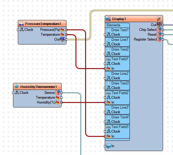
Step 6: In Visuino Connect Components

- Connect “PressureTemperature1” pin [Out] to Arduino I2C [In]
- Connect “PressureTemperature1” pin [Pressure] to Display1>TextField3 [In]
- Connect “PressureTemperature1” pin [Temperature] to Display1>TextField1 [In]
- Connect “HumidityThermometer1” pin [Humidity] to Display1>TextField2 [In]
- Connect “HumidityThermometer1” pin [Out] to Arduino digital pin [7]
- Connect “Display1” component pin [Out] to Arduino pin SPI [In]
- Connect “Display1” component pin [Chip Select] to Arduino Digital pin[10]
- Connect “Display1” component pin [Reset] to Arduino Digital pin[8]
- Connect “Display1” component pin [Register Select] to Arduino Digital pin[9]
Step 7: Generate, Compile, and Upload the Arduino Code

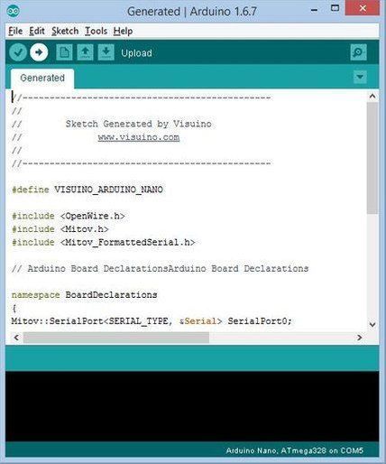
In Visuino, Press F9 or click on the button shown on Picture 1 to generate the Arduino code, and open the Arduino IDE
In the Arduino IDE, click on the Upload button, to compile and upload the code (Picture 2)
Step 8: Play
If you power the Arduino UNO module, the LCD will start to show current values (TEMPERATURE,HUMIDITY,PRESSURE)
Congratulations! You have completed your project with Visuino. Also attached is the Visuino project, that I created for this Instructable, you can download it here and open it in Visuino: https://www.visuino.eu
Read Full tutorial here.