In this tutorial we will learn how to Find out when someone entered a room using RTC module, PIR sensor,OLED display and arduino.
Watch a demonstration video.
Step 1: What You Will Need

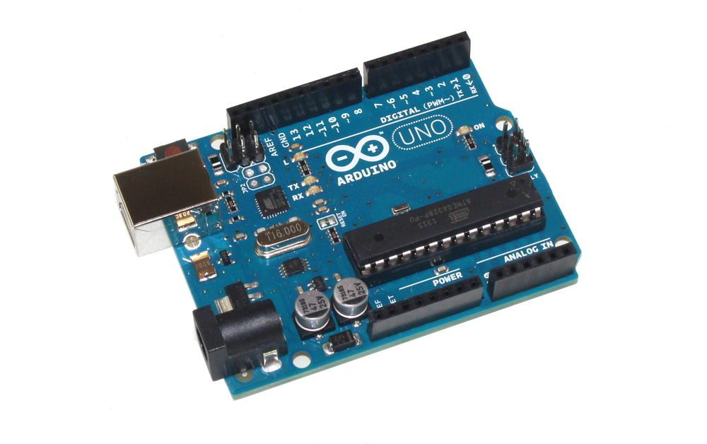
- Arduino UNO (or any other Arduino)
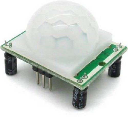
- PIR Sensor
- RTC DS1307 Real Time Clock module
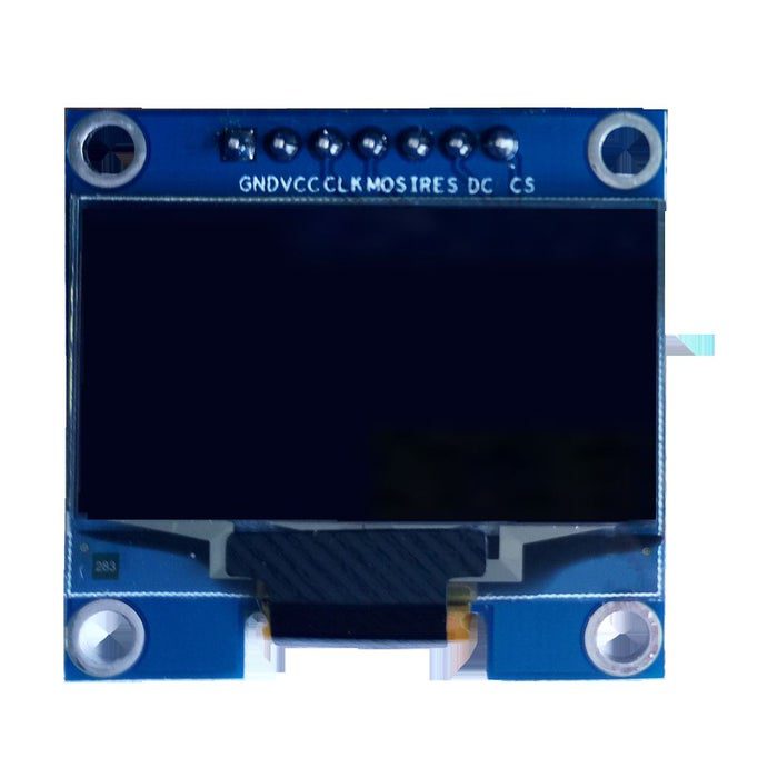
- OLED display
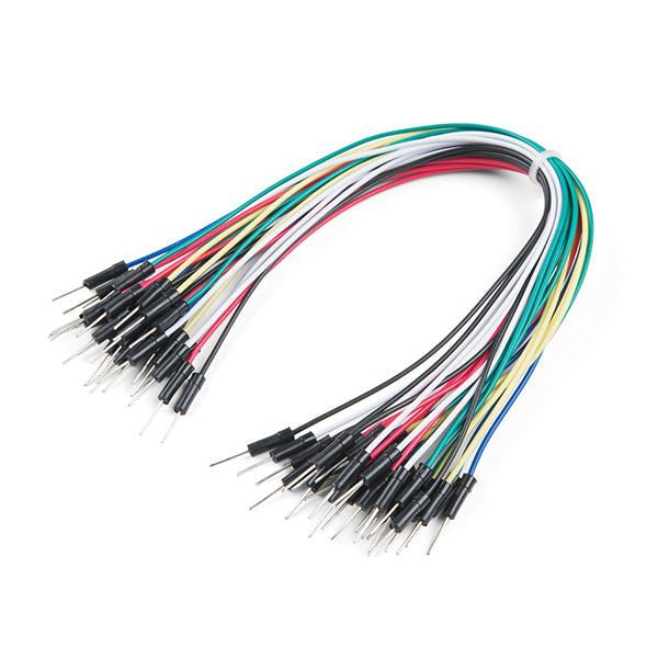
- Jumper wires
- Visuino program: Download Visuino
Step 2: The Circuit
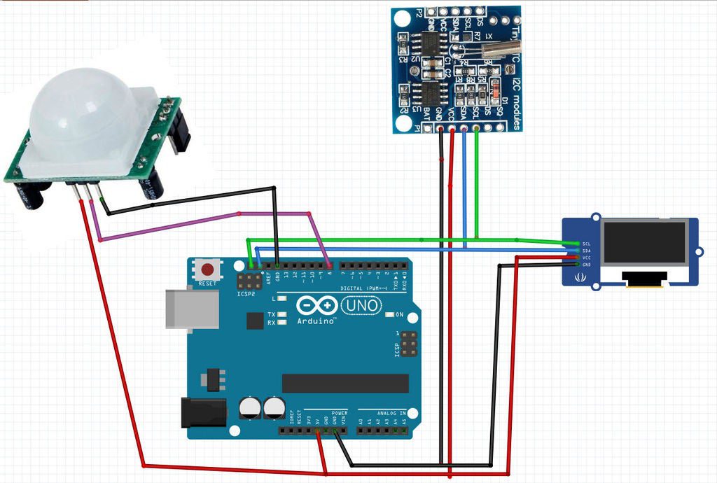
- Connect PIR sensor pin [GND] to Arduino pin [GND]
- Connect PIR sensor pin [VCC] to Arduino pin [5V]
- Connect PIR sensor pin [Signal] to Arduino digital pin [8]
- Connect RTC module pin [GND] to Arduino pin [GND]
- Connect RTC module pin [VCC] to Arduino pin [5V]
- Connect RTC module pin [SDA] to Arduino pin [SDA]
- Connect RTC module pin [SCL] to Arduino pin [SCL]
- Connect OLED Display pin [GND] to Arduino pin [GND]
- Connect OLED Display pin [VCC] to Arduino pin [5V]
- Connect OLED Display pin [SDA] to Arduino pin [SDA]
- Connect OLED Display pin [SCL] to Arduino pin [SCL]
Step 3: Start Visuino, and Select the Arduino UNO Board Type
To start programming the Arduino, you will need to have the Arduino IDE installed from here: https://www.arduino.cc/.
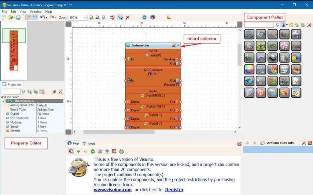
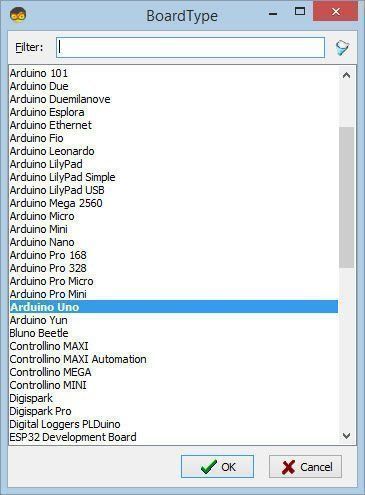
Please be aware that there are some critical bugs in Arduino IDE 1.6.6. Make sure that you install 1.6.7 or higher, otherwise this Instructable will not work! If you have not done follow the steps in this Instructable to setup the Arduino IDE to program Arduino UNO! The Visuino: https://www.visuino.eu also needs to be installed. Start Visuino as shown in the first picture Click on the “Tools” button on the Arduino component (Picture 1) in Visuino When the dialog appears, select “Arduino UNO” as shown on Picture 2
Step 4: In Visuino Add Components


- Add “Real Time Clock(RTC) DS1307” component
- Add “SSD1306/SH1106 OLED Display (I2C)” component
- Add “Digital (Boolean) Change Only” component
- Add “Detect Edge” component
- Add “Clock On/Off Switch” component
- Add “Timer” component
In the properties window Set “Interval (uS)” to 10000000
This means that the sensor will “sleep” for 10s (10000000uS) after every detection, this will prevent multiple timestamps at once, Ideally you would set this to something like 5min - Add “Inverter” component
Step 5: In Visuino Connect Components
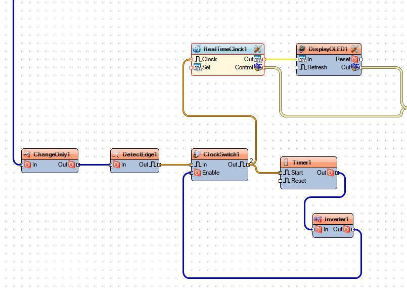
- Connect Arduino digital Out pin [8] to “ChangeOnly1” pin [In]
- Connect “ChangeOnly1” pin [Out] to “DetectEdge1” pin [In]
- Connect “DetectEdge1” pin [Out] to “ClockSwitch1” pin [In]
- Connect “ClockSwitch1” pin [Out] to “RealTimeClock1” pin [Clock] and “Timer1” pin [Start]
- Connect “Timer1” pin [Out] to “Inverter1” pin [In]
- Connect “Inverter1” pin [Out] to “ClockSwitch1” pin [Enable]
- Connect “RealTimeClock1” pin [Control] to Arduino I2C [In]
- Connect “RealTimeClock1” pin [Out] to “DisplayOLED1” pin [In]
- Connect “DisplayOLED1” pin [Control] to Arduino I2C [In]
Step 6: Generate, Compile, and Upload the Arduino Code

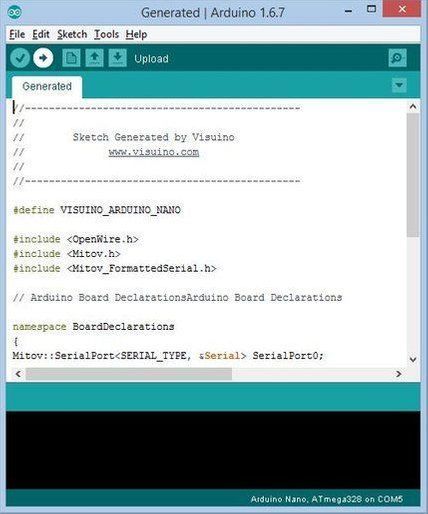
In Visuino, Press F9 or click on the button shown on Picture 1 to generate the Arduino code, and open the Arduino IDE
In the Arduino IDE, click on the Upload button, to compile and upload the code (Picture 2)
Step 7: Play
If you power the Arduino UNO module, and make a move the PIR sensor should detect it and make a timestamp on the OLED Display. Depending on the interval that you set in the Timer component it should detect another movement after that time passes.
Congratulations! You have completed your project with Visuino. Also attached is the Visuino project, that I created for this Instructable, you can download it here and open it in Visuino: https://www.visuino.eu
Read Full tutorial here.